Difference between revisions of "LCD Terminal"
(→Microcontroller) |
(→Result: filename) |
||
| (10 intermediate revisions by the same user not shown) | |||
| Line 10: | Line 10: | ||
=== Microcontroller === | === Microcontroller === | ||
| − | As I mentioned already, I wanted to get to know PIC microcontrollers a bit more. For that reason I chose a small 8-bit controller with flash memory and low pin-count: a 16F628A. | + | As I mentioned already, I wanted to get to know PIC microcontrollers a bit more. For that reason I chose a small 8-bit controller with flash memory and low pin-count: a '''16F628A'''. |
One important feature of this microcontroller family that it includes an internal 4MHz oscillator, which means I don't have to include clock generation circuitry. | One important feature of this microcontroller family that it includes an internal 4MHz oscillator, which means I don't have to include clock generation circuitry. | ||
| + | |||
| + | To flash new software into the PIC I required a flash programmer. The official in-circuit debugger (ICD) from Microchip was too expensive for this little project, so I decided to build a programmer on my own. I made a programmer similar to [http://www.sprut.de/electronic/pic/brenner/index.htm#brenner5 Brenner5] from Sprut's homepage (you can find more details under [[PIC programmer]]). | ||
=== Schematic === | === Schematic === | ||
| + | As much as I'd love to present the schematic here, I'm unable to do so because the file was lost in a hard disk failure :( | ||
| + | |||
=== Printed Circuit Board === | === Printed Circuit Board === | ||
| + | For this PCB I decided to try [[Wikipedia:Eagle (program)|Eagle]] from [http://www.cadsoft.de/ Cadsoft] for the first time. | ||
| + | |||
| + | The first attempt was that I created a PCB layout in Eagle and printed it on a sheet of paper. I then tried to copy that manually onto a blank PCB: | ||
| + | |||
| + | [[File:DisplayPIC board1.jpg|none|300px]] | ||
| + | |||
| + | But when I then put the board into the etching solution, the following happened: | ||
| + | |||
| + | [[File:DisplayPIC board1 fail.jpg|300px]] | ||
| + | |||
| + | I did some additional reading and finally decided that I wanted to spend my time on microcontroller programming, not on PCB fabrication. So the second attempt was using a simple hole pattern board (the layout was still done in Eagle): | ||
| + | |||
| + | [[File:DisplayPIC board2.jpg|300px]] | ||
| + | |||
| + | On the top side you can see the ''In-circuit Serial Programming (ICSP)'' connector, used for programming and for power supply. The ribbon cable to the left attaches a serial [[Wikipedia:D-subminiature|D-sub connector]] and the ribbon cable to the right connects the display. | ||
| + | |||
== Code == | == Code == | ||
| + | == Result == | ||
| + | The circuit and the program finally worked! It does not have much practical use, because the display is much too small and the boot process of a Linux much too fast for a serial connection with 9600 baud. But I had fun in developing it and that is all that matters: | ||
| + | |||
| + | <gallery> | ||
| + | File:DisplayPIC_final.jpg|the complete circuit in operation | ||
| + | File:DisplayPIC_display.jpg|the display showing the startup "screen" | ||
| + | </gallery> | ||
[[Category:Electronics]] | [[Category:Electronics]] | ||
Latest revision as of 20:55, 12 June 2011
When playing around with Linux on an embedded PC I noticed that the Linux kernel has the ability to output its startup log messages to a serial port. This fascinated me very much because I did not intent to run that embedded PC with a computer screen.
Also I was working on an embedded TCP/IP stack at that time (2002) and was looking for some way to find out what Ethernet frames and IP datagrams my stack is receiving.
So the idea came to me to build an LCD terminal. I had an LCD display with 2 lines with 20 characters each and was looking for some project to familiarize myself with PIC microcontrollers. With the Linux startup messages in mind I wanted to see all these messages scrolling over my display.
Contents
Components
Display
The display I got was a 20x2 character dot-matrix display with green backlight. It has an HD44780-compatible controller and a 16-pin interface. I used a ribbon cable with IDC connector to connect my microcontroller board.
Microcontroller
As I mentioned already, I wanted to get to know PIC microcontrollers a bit more. For that reason I chose a small 8-bit controller with flash memory and low pin-count: a 16F628A.
One important feature of this microcontroller family that it includes an internal 4MHz oscillator, which means I don't have to include clock generation circuitry.
To flash new software into the PIC I required a flash programmer. The official in-circuit debugger (ICD) from Microchip was too expensive for this little project, so I decided to build a programmer on my own. I made a programmer similar to Brenner5 from Sprut's homepage (you can find more details under PIC programmer).
Schematic
As much as I'd love to present the schematic here, I'm unable to do so because the file was lost in a hard disk failure :(
Printed Circuit Board
For this PCB I decided to try Eagle from Cadsoft for the first time.
The first attempt was that I created a PCB layout in Eagle and printed it on a sheet of paper. I then tried to copy that manually onto a blank PCB:

But when I then put the board into the etching solution, the following happened:

I did some additional reading and finally decided that I wanted to spend my time on microcontroller programming, not on PCB fabrication. So the second attempt was using a simple hole pattern board (the layout was still done in Eagle):

On the top side you can see the In-circuit Serial Programming (ICSP) connector, used for programming and for power supply. The ribbon cable to the left attaches a serial D-sub connector and the ribbon cable to the right connects the display.
Code
Result
The circuit and the program finally worked! It does not have much practical use, because the display is much too small and the boot process of a Linux much too fast for a serial connection with 9600 baud. But I had fun in developing it and that is all that matters:
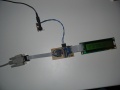
the complete circuit in operation
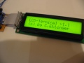
the display showing the startup "screen"

