Difference between revisions of "USB SNES Controller"
(→Prototype: renamed file) |
(→Prototype: added pin assignments) |
||
| Line 29: | Line 29: | ||
[[File:SNESUSB_prototype_design.png|none|300px]] | [[File:SNESUSB_prototype_design.png|none|300px]] | ||
[[File:SNESUSB_prototype.jpg|none|300px]] | [[File:SNESUSB_prototype.jpg|none|300px]] | ||
| + | |||
| + | To the left (CON3) you can see a [[Wikipedia:D-subminiature|DB-9 connector]] for connecting the controller (in the prototype I used a connector so I could easily change the controllers). The pin assignment is as follows: | ||
| + | |||
| + | {| border="1" | ||
| + | ! DB9 pin !! wire color !! signal | ||
| + | |- | ||
| + | | 2 || red || Data | ||
| + | |- | ||
| + | | 3 || orange || Latch | ||
| + | |- | ||
| + | | 4 || yellow || Clock | ||
| + | |- | ||
| + | | 6 || white || +5V supply voltage | ||
| + | |- | ||
| + | | 8 || brown || Ground | ||
| + | |} | ||
| + | |||
| + | To the top (CON1) one can find the ICSP connector for programming the microcontroller. This connector has the following pin assignment: | ||
| + | |||
| + | {| border="1" | ||
| + | ! pin !! signal | ||
| + | |- | ||
| + | | 1 || +12V programming voltage (Vpp) | ||
| + | |- | ||
| + | | 2 || +5V supply voltage (Vdd) | ||
| + | |- | ||
| + | | 3 || Ground (Vss) | ||
| + | |- | ||
| + | | 4 || Data (PGD) | ||
| + | |- | ||
| + | | 5 || Clock (PGC) | ||
| + | |} | ||
= Final = | = Final = | ||
[[Category:Electronics]] | [[Category:Electronics]] | ||
Revision as of 19:47, 13 June 2011
During my childhood I used to play many great games on the Super Nintendo (SNES). Many years later, I heard of snes9x and played a few of these games again on my PC. What always annoyed me was the controller: it was nearly impossible to play these games with the keyboard.

I bought a few gamepads then, but still, they were missing some more or less important keys compared to the original SNES controller and the real "Nintendo feeling" never came up. (See, back then, USB did not exist yet. Instead, joysticks and gamepads had this 15-pin D-sub connector that you had to plug into your soundcard, and calibration also for gamepads was crucial because inputs were still analog.)
Many years later, the idea struck me to program a microcontroller to interface with an original SNES controller on the one hand, and provide a standard USB HID interface on the other hand, so that it could be used with any PC, any operating system and without the need for additional drivers.
The vision I had in mind was a circuit so small that I could hide it in a standard USB connector. The result would be an SNES controller with a USB plug. I did not want to modify the electronics within the controller itself so it would still be usable on a normal SNES.
Components
SNES controller
I bought an old Super Nintendo on ebay and had a look on the controllers:

the controller has standard rubber contacts like any TV remote
the board contains the contact plates and one IC


You can find all details on the controller's schematic, pin assignment and communication protocol on a separate page: SNES Controller.
Microcontroller
The microcontroller I chose for this project was one of the smallest PICs which has USB support: PIC18F2450 with 28 pins.
Code
Prototype
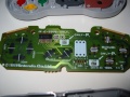
I created a first prototype on a hole pattern board for developing the code and easy debugging. The board layout was done with Eagle.


To the left (CON3) you can see a DB-9 connector for connecting the controller (in the prototype I used a connector so I could easily change the controllers). The pin assignment is as follows:
| DB9 pin | wire color | signal |
|---|---|---|
| 2 | red | Data |
| 3 | orange | Latch |
| 4 | yellow | Clock |
| 6 | white | +5V supply voltage |
| 8 | brown | Ground |
To the top (CON1) one can find the ICSP connector for programming the microcontroller. This connector has the following pin assignment:
| pin | signal |
|---|---|
| 1 | +12V programming voltage (Vpp) |
| 2 | +5V supply voltage (Vdd) |
| 3 | Ground (Vss) |
| 4 | Data (PGD) |
| 5 | Clock (PGC) |