Difference between revisions of "USB SNES Controller"
(→PCB) |
m (changed layout of snes9x screenshot) |
||
| Line 1: | Line 1: | ||
| + | [[File:snes9x_joypad.png|thumb|300px|gamepad configuration in [http://www.snes9x.com snes9x] - it's simply not fun to play SNES games on a keyboard]] | ||
During my childhood I used to play many great games on the [[Wikipedia:Super Nintendo Entertainment System|Super Nintendo (SNES)]]. Many years later, I heard of [http://www.snes9x.com snes9x] and played a few of these games again on my PC. What always annoyed me was the controller: it was nearly impossible to play these games with the keyboard. | During my childhood I used to play many great games on the [[Wikipedia:Super Nintendo Entertainment System|Super Nintendo (SNES)]]. Many years later, I heard of [http://www.snes9x.com snes9x] and played a few of these games again on my PC. What always annoyed me was the controller: it was nearly impossible to play these games with the keyboard. | ||
| − | |||
| − | |||
I bought a few [[Wikipedia:Gamepad|gamepads]] then, but still, they were missing some more or less important keys compared to the original SNES controller and the real "Nintendo feeling" never came up. (See, back then, USB did not exist yet. Instead, joysticks and gamepads had this 15-pin D-sub connector that you had to plug into your soundcard, and calibration also for gamepads was crucial because inputs were still analog.) | I bought a few [[Wikipedia:Gamepad|gamepads]] then, but still, they were missing some more or less important keys compared to the original SNES controller and the real "Nintendo feeling" never came up. (See, back then, USB did not exist yet. Instead, joysticks and gamepads had this 15-pin D-sub connector that you had to plug into your soundcard, and calibration also for gamepads was crucial because inputs were still analog.) | ||
Revision as of 14:28, 14 June 2011

During my childhood I used to play many great games on the Super Nintendo (SNES). Many years later, I heard of snes9x and played a few of these games again on my PC. What always annoyed me was the controller: it was nearly impossible to play these games with the keyboard.
I bought a few gamepads then, but still, they were missing some more or less important keys compared to the original SNES controller and the real "Nintendo feeling" never came up. (See, back then, USB did not exist yet. Instead, joysticks and gamepads had this 15-pin D-sub connector that you had to plug into your soundcard, and calibration also for gamepads was crucial because inputs were still analog.)
Many years later, the idea struck me to program a microcontroller to interface with an original SNES controller on the one hand, and provide a standard USB HID interface on the other hand, so that it could be used with any PC, any operating system and without the need for additional drivers.
The vision I had in mind was a circuit so small that I could hide it in a standard USB connector. The result would be an SNES controller with a USB plug. I did not want to modify the electronics within the controller itself so it would still be usable on a normal SNES.
Contents
Components
SNES controller
I bought an old Super Nintendo on ebay and had a look on the controllers:

the controller has standard rubber contacts like any TV remote
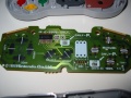
the board contains the contact plates and one IC


You can find all details on the controller's schematic, pin assignment and communication protocol on a separate page: SNES Controller.
Microcontroller
The microcontroller I chose for this project was one of the smallest PICs which has USB support: PIC18F2450 with 28 pins.
Code
Prototype
I created a first prototype on a hole pattern board for developing the code and easy debugging. The board layout was done with Eagle.
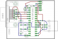
prototype board design
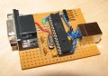
prototype on hole pattern board


To the left (CON3) you can see a DB-9 connector for connecting the controller (in the prototype I used a connector so I could easily change the controllers). The pin assignment is as follows:
| DB9 pin | wire color | signal |
|---|---|---|
| 2 | red | Data |
| 3 | orange | Latch |
| 4 | yellow | Clock |
| 6 | white | +5V supply voltage |
| 8 | brown | Ground |
To the top (CON1) one can find the ICSP connector for programming the microcontroller. This connector has the following pin assignment:
| pin | signal |
|---|---|
| 1 | +12V programming voltage (Vpp) |
| 2 | +5V supply voltage (Vdd) |
| 3 | Ground (Vss) |
| 4 | Data (PGD) |
| 5 | Clock (PGC) |
Final Version
When the experiments with the prototype were successful, I started to develop the final, miniaturized version.
Schematic
The board layout for the final version was done with eagle, for that I first drew the schematic:

The wirepads to the left (labeled with YELLOW, ORANGE, RED, WHITE and BROWN) are the holes where the controller wires will be soldered. The wirepads labeled with PADx are solder pads where the wires for ICSP will be soldered: PAD1=PGC, PAD2=PGD, PAD3=VPP. Ground and supply voltage must always be connected through the USB connector.
USB requires a highly-accurate clock, which can only be retrieved from a crystal or a ceramic resonator. A crystal would be much too big for my small board, so I chose a CSTCC ceramic resonator from muRata. This has the additional advantage that it already includes the two load capacitors, which again helps to save board space.
The PIC18F2450 microcontroller is also available in a QFN package. Although this is quite difficult to solder (I tried several methods) it is the smallest possible alternative.
The only other external parts are two capacitors: C1 for smoothing the supply voltage and C2, which is required for USB 3.3V generation. Note that no pull-up resistors can be found in the schematic: the PIC18F2450 contains internal pull-ups for that purpose (this fact was completely omitted from the original data sheet 39760a.pdf, it can only be found in the errata 80274a.pdf)!
PCB
As I said, I wanted the board to be so small that it could fit into the plug's casing. This made it quite difficult to route all signals, but in the end I succeeded:

The PCB layout is a double-sided layout with parts only on the top side (red), and traces on both sides, connected with vias (green). The solder pads for ICSP are on the bottom side (blue). To the right you can see five bigger holes, these are used to connect the wires of the SNES controller.
This kind of PCB is impossible to manufacture at home, so I enlisted the services of http://www.pcb-pool.com. This manufacturer also provides and Eagle rule-file, which helps you to avoid layouts that can't be manufactured. After a few days I got the results, and I can tell you, I was very satisfied:
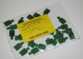
delivery from PCB-POOL
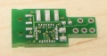
final PCB, top side
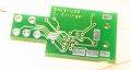
final PCB, bottom side


Soldering the parts on such a small PCB is a bit tricky, especially the QFN-packaged microcontroller. I tried several approaches, but the way that worked best was the following:
- apply solder paste to all pads - the solder resist between the pads ensures that no pads or vias get short-connected that shouldn't
- place the parts on the board, the solder paste holds them in place
- carefully heat up the PCB with a soldering torch (gas burner)